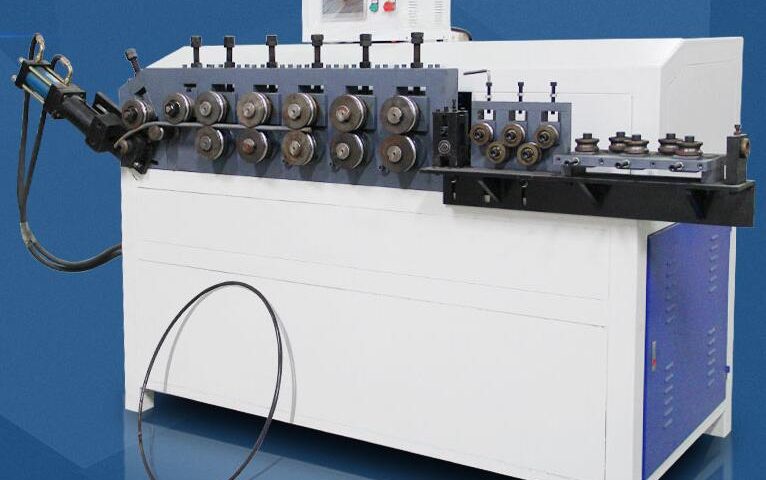
Anti-interference Laser Welding Tracker for Circumferencial Welding Machine

1. Introduction:
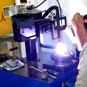
Our system software uses super linear laser to accumulate in the observation position.
At this time, the line laser brightness is greater than the welding arc. Industrial camera input the laser line shape to the computer. Position of weld is obtained by computer analysis and outputted to the actuator to guide or track the correction.
2.Advantages:
1.It can track both left and right, up and down without touching at the same time, and ensure that the welding position is accurate and the welding current is stable
2.Due to the use of special laser and photo control, it has super strong anti-interference and high stability.
3.The interval between tracking point and welding point is 2cm, real-time tracking.
4. Basically no maintenance required (wipe off the dust or replace the lens cover)

3.Parameter of machine
1. The power of this machine is 1000W.
2. it can adapt to track the left and right distance 30mm, up or down 30mm, or customize special needs.
3. The tracking speed is in line with the speed requirement of ring welding, or greater than 2 m/min.
4. It is suitable for lap or splice welding with weld more than 0.2mm. The width of the corner weld seam is not limited.
5. Recognition accuracy: 0.2mm
6. The response speed of weld recognition: 0.2S.
7. Support welding speed: 0~2000mm/min
8. Support welding types: gas shielded arc welding, argon arc welding, plasma welding and laser welding.

The whole system including computer, industrial camera, laser line, X/Y adjusting mechanism, hood, software etc.
Now, the system is widely used in welding production of stainless steel, sheet metal and process decorative parts as welding seam tracking and guidance.

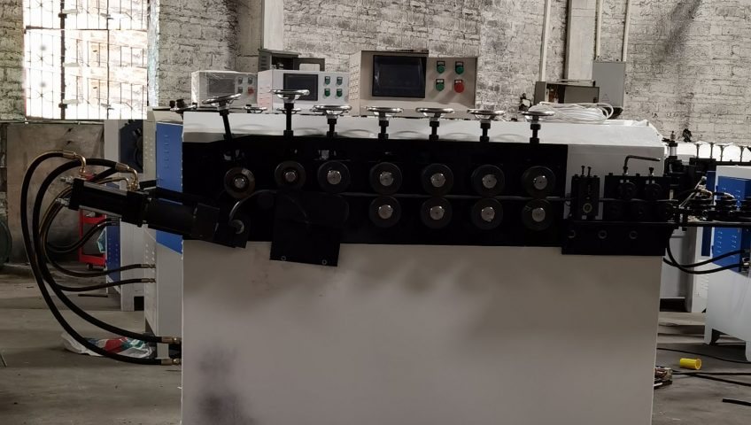
Preparations for The Installation and Operation of The Ring Forming Machine

Preparations for the installation and operation of the ring forming machine

  1. Connect the three-phase 380V AC power supply.
  2. Turn on the cooling water.
  3. Fill 68# anti-wear oil hydraulic oil into the oil tank to the position of 2 / 3 of the oil gauge.
  4. Turn (open) the red emergency stop switch clockwise.
  5. Turn on the boat switch I / O (press the switch to on)

Note: after connecting the power line, turn on the switch and press manual cutter. If the cutter does not act, replace any two of the three phases of the power supply to work normally.

Open the rear door cover, open the valve of the pressure gauge, and the pressure will be seen on the pressure gauge.

Adjust different pressures according to different wire diameters.

When adjusting the pressure, use a 6mm Allen wrench to rotate the Allen nut at the top of the oil pump, clockwise to pressurize and counterclockwise to depressurize.

After adjusting the pressure, close the valve of the pressure gauge to prevent the oil pressure from being too high and breaking through the oil pressure gauge under load, resulting in oil leakage.

Pay attention to check the oil pressure parameters:

Wire diameter: 1-3.5 (mm), pressure: 25-30 (kg)

Wire diameter: 3.5-6 (mm), pressure: 30-50 (kg)

Wire diameter: 6-8 (mm), pressure: 50-70 (kg)

Common Fault Causes And Troubleshooting (Maintenance Methods) Of Tungsten Argon Arc Welding Machine/TIG Welding

Common Fault Causes And Troubleshooting (Maintenance Methods) Of Tungsten Argon Arc Welding Machine/TIG Welding

Tungsten inclusion

  1. Contact arc striking (arc striking with high frequency oscillator or high voltage pulse generator).
  2. Tungsten electrode melting (. Reduce welding current or increase tungsten electrode diameter, tighten tungsten electrode collet and reduce tungsten electrode extension length; replace cracked or torn tungsten electrode).

Poor gas protection effect

  1. The purity of protective gas is low (argon with purity (volume fraction) of 99.99% is used).
  2. The air supply in advance and lag time are short (there are enough air supply in advance and lag time).
  3. Insufficient gas flow (increase gas flow).
  4. The gas pipe is damaged and leaking (repair the damaged gas pipe).

Arc instability

  1. There is oil stain on the weldment (clean the weldment).
  2. The joint groove is too narrow (widen the joint groove and shorten the arc length).
  3. Tungsten electrode pollution (remove the polluted part of tungsten electrode).
  4. The tungsten electrode diameter is too large (use the correct tungsten electrode and collet).
  5. The arc length is too long (lower the nozzle distance and shorten the arc length).

Tungsten electrode loss is too fast

  1. Poor gas protection and tungsten electrode oxidation (clean the nozzle, shorten the nozzle distance and appropriately increase the argon flow).
  2. Reverse polarity connection (increase the tungsten electrode diameter or change to positive polarity connection).
  3. The collet is overheated and deformed (polish the tungsten electrode and replace the collet).
  4. The diameter of tungsten electrode is too small (replace with large diameter tungsten electrode).
  5. When welding is stopped, the tungsten electrode is oxidized (increase the lag air supply time, not less than 1s / 10A).

What Should Be Paid Attention To When Welding Flanges And Pipes?

What Should Be Paid Attention To When Welding Flanges And Pipes?

  1. The flange contact surface should be smooth, annular shallow groove can be allowed, but there shall be no spot scar, sand hole and radiation to the groove, the two flange surface evenly and strictly contact.
  2. The center line of the flange plane shall be perpendicular to the center line of the pipe, and the deviation shall not be greater than 1-2.5mm.
  3. Flange screw hole distance position (linear measurement) allowable error 0.5-1.0mm.
  4. The allowable displacement error between flange hole center line and pipe center line is 1-2mm.
  5. The allowable deviation of the two flanges is 0.2-0.3mm.
  6. When welding flange and pipe, attention should be paid to welding stress deformation (especially stainless steel). To ensure the verticality of the flange and the pipeline, avoid two flanges in bolt connection flange parallelism deviation is too large, resulting in gasket clamping and leakage.

Automatic Welding of Corrugated Metal Hose

Automatic Welding of Corrugated Metal Hose

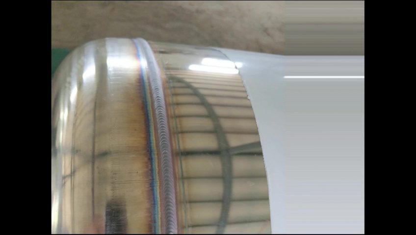
Corrugated metal hose (bellows Corrugated pipe) is an important flexible pipe in modern industrial pipeline. In various gas transmission and infusion pipeline systems and length, temperature, position and angle compensation systems, as compensation elements, sealing elements, connecting elements and damping elements, they are widely used in aerospace, petrochemical industry, mining electronics, machinery and shipbuilding, medical and health, light textile electronics, energy construction and other fields.

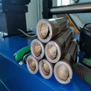
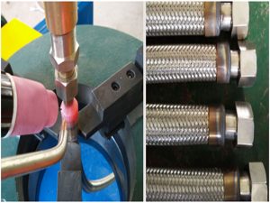
Corrugated metal hose is mainly composed of corrugated pipe, mesh sleeve and joint, as shown in Figure 1. The inner pipe is a thin-walled stainless steel bellows with spiral or annular waveform. The mesh sleeve of the outer layer of the bellows is woven by stainless steel wire or steel strip according to certain parameters. The joints at both ends of the hose are either flanges or screw heads, with various forms, which vary according to the application conditions.
1. The welding process of corrugated metal hose generally includes two processes:

(1) Welding of mesh sleeve, corrugated pipe and compression sleeve – metal hose body;

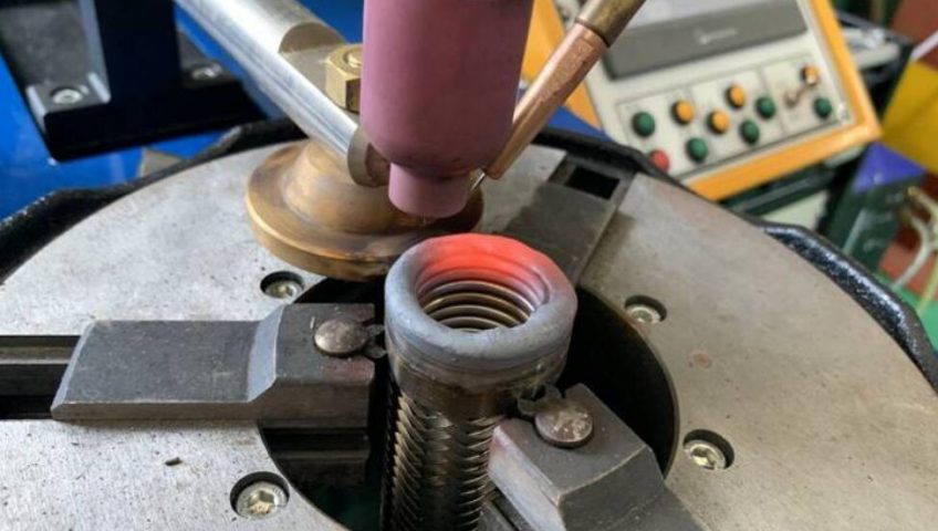
(2) Welding of metal hose body and pipe joint.

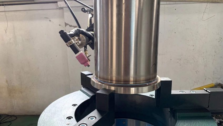
Automatic corrugated metal hose welding machine

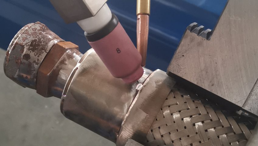
The metal hose body is a three-layer structure, namely mesh sleeve, corrugated pipe and compression sleeve, The assembly quality and welding process before welding are strict, and the precision of automatic welding machine is high.

The equipment has the function of automatic tracking of longitudinal and transverse welds. It can track the non roundness of compression sleeve and the height runout of mesh sleeve and bellows end face in real time, so as to ensure the stability of welding process and welding process. The practical application shows that the equipment has high degree of automation, accurate positioning of welding gun, flexible process adjustment, high repeatability and stable welding quality

Automatic Metal Hose Joints (Flange) Welding Machine

Automatic Metal Hose Joints (Flange) Welding Machine

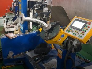
Automatic welding machine for metal hose joints, welding gun and displacement mechanism can realize flexible angle adjustment, so that the equipment has wide adaptability and can complete the welding of most existing pipe joints such as flanges, elbows and wire heads.

Key points of welding process

1 Key points of metal hose body welding process

(1) Due to the special three-layer structure of the metal hose body and the poor repeatability of pre welding assembly, the welding process must have enough tolerance window.

(2) Because thin-walled parts are very sensitive to welding line energy, the welding process requires accurate control of welding current and welding voltage, and must be matched with the amount of wire filling.

2.key points of metal hose joint welding process

Generally specking, the thickness of hose joint and compression pipe sleeve is quite different, and the types of pipe joint are diverse. Therefore, the influence of welding angle on weld formation and quality should be fully considered in the welding process.

Conclusion

  • Corrugated metal hose has a wide range of applications and large dosage. Its working temperature range can reach – 196 ℃ ~ + 420 ℃, and the pressure range is generally pN0 6-32.0mpa, up to 42.0mpa, with high weld quality requirements.
  •  Due to the special multi-layer structure of metal hose, in order to ensure the welding quality, higher requirements are put forward for the butt joint quality before welding, welding process and welding equipment.
  • Automaticwelding process are developed for corrugated metal hose welding industry, with high degree of automation, stable process parameter control, strong process adaptability and good practical application effect
  •  

Operation and adjustment of the Ring forming machine

Operation And Adjustment Of The Ring Forming Machine

Adjustment and use of looping machine: when the machine is powered on and can operate normally, we need to adjust the machine to make it work better for us.

  1. First, according to the operation process of the electric control box, send the wire to the cutter. Adjust the position of the forming wheel and cutter to make the arc of the product meet the requirements. At the same time, adjust the cutter so that the axis of the cutter passes the center of the product.
  2. The flatness of the product can be adjusted by adjusting the position of the forming wheel (in and out of the vertical plane).
  3. If the outgoing line of the product runs inward and outward from time to time, the wire adjusting wheel on the wire adjusting board needs to be adjusted to increase the straightening of the wire. (Most of the above situations are caused by poor wire workpiece. Just increase the straightening force of wire workpiece).
  4. If the equipment needs to be reversed when it is running, the speed regulating switch should be reset first, and the machine can be started after shutdown for 1 minute;
  5. When feeding the dynamic pressure wheel, loosen the fastening bolts first, and fix the bolts on both sides of the driven wheel after the feeding reaches the scale; 6. In the process of use, the miscellaneous stains in the pressure roller groove and the surface of the workbench shall be cleaned in time.